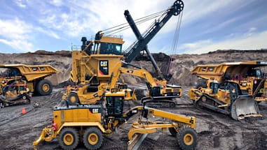
With our huge inventory of new, used and rental equipment, WesTrac has the right machine for the job.
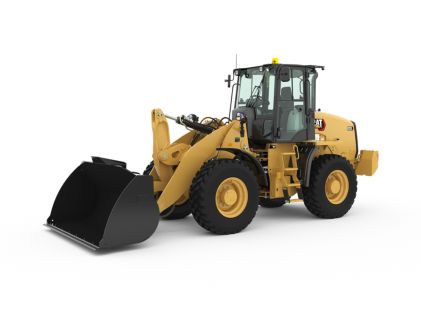
Wheel Loaders
Compare Models

UNITS:
Metric
Imperial
Engine
Rated Net Power - Rated Engine Speed
2200 r/min
2200 r/min
2200 r/min
2200 r/min
2400 r/min
2400 r/min
Maximum Gross Power - Rated Engine Speed
2200 r/min
2200 r/min
-
2400 r/min
2400 r/min
Rated Net Power - SAE J1349
90 kW
120 hp
73 kW
98 hp
54.4 kW
73 hp
Maximum Gross Power - ISO 14396 (metric)
122 hp
122 hp
-
75.3 mhp
75.3 mhp
Rated Net Power - ISO 9249
88 kW
118 hp
74 kW
99 hp
53.8 kW
72.1 hp
Maximum Gross Torque - SAE J1995
505 N·m
372 ft·lbf
415 N·m
306 ft·lbf
301 N·m
222 lb/ft
Maximum Gross Torque - ISO 14396
500 N·m
369 ft·lbf
410 N·m
302 ft·lbf
300 N·m
221 lb/ft
Maximum Net Torque - SAE J1349
496 N·m
366 ft·lbf
400 N·m
295 ft·lbf
296 N·m
218 lb/ft
Maximum Net Torque - ISO 9249
493 N·m
363 ft·lbf
405 N·m
299 ft·lbf
295 N·m
217 lb/ft
Displacement
3.6 l
220 in³
4.4 l
268 in³
2.8 l
171 in³
Bore
98 mm
3.85 in
105 mm
4.13 in
90 mm
3.54 in
Stroke
120 mm
4.72 in
127 mm
5 in
110 mm
4.33 in
Engine Model
Cat C3.6
Cat C3.6
Cat C4.4
Cat C4.4
Cat C2.8*
Cat C2.8*
Emissions
Engine meets Tier 4 Final/Stage V emission standards.
Engine meets Tier 4 Final/Stage V emission standards.
Engine meets Brazil MAR-1 emission standards, equivalent to U.S. EPA Tier 3/EU Stage IIIA.
Engine meets Brazil MAR-1 emission standards, equivalent to U.S. EPA Tier 3/EU Stage IIIA.
-
Note
Net power advertised is the power available at the flywheel plus front drive implement pump when the engine is equipped with fan, air cleaner, muffler and alternator.
Net power advertised is the power available at the flywheel plus front drive implement pump when the engine is equipped with fan, air cleaner, muffler and alternator.
Net power advertised is the power available at the flywheel plus front drive implement pump when the engine is equipped with fan, air cleaner, muffler and alternator.
Net power advertised is the power available at the flywheel plus front drive implement pump when the engine is equipped with fan, air cleaner, muffler and alternator.
*Equivalent to U.S. EPA Tier 3 and EU Stage IIIA.
*Equivalent to U.S. EPA Tier 3 and EU Stage IIIA.
Maximum Gross Power - ISO 14396
90 kW
121 hp
75 kW
100 hp
55.4 kW
74.3 hp
Maximum Gross Power
90 kW
121 hp
75 kW
100 hp
60 kW
75.1 hp
Maximum Gross Power - Maximum Engine Speed
-
2350 r/min
2350 r/min
-
Maximum Gross Power - SAE J1995
-
76 kW
102 hp
60 kW
75.1 hp
Maximum Gross Power - ISO 14396 (DIN)
-
75 kW
102 hp
-
Rated Net Power - ISO 9249 (DIN)
-
74 kW
101 hp
-
Maximum Engine Speed
-
-
2550 rpm
2550 rpm
Rated Net Power - 2,400 rpm - ISO 9249 (metric)
-
-
73.1 mhp
73.1 mhp
Note (1)
-
-
Maximum gross and net torque measured at 1,600 rpm.
Maximum gross and net torque measured at 1,600 rpm.
Note (2)
-
-
Net power ratings are tested at the reference conditions for the specified standard.
Net power ratings are tested at the reference conditions for the specified standard.
Note (3)
-
-
Net power advertised is the power available at the flywheel.
Net power advertised is the power available at the flywheel.
Buckets
Bucket Capacities
1.3-3.5 m3 (1.7-4.6 yd3)
1.3-3.5 m3 (1.7-4.6 yd3)
1.6-3.5 m3 (2.1-4.6 yd3)
1.6-3.5 m3 (2.1-4.6 yd3)
0.75-1.55 m³ (1.0-2.0 yd³)
0.75-1.55 m³ (1.0-2.0 yd³)
Bucket Capacities - General Purpose
1.3-1.9 m³ (1.7-2.5 yd³)
1.3-1.9 m³ (1.7-2.5 yd³)
-
0.80-1.35 m³ (1.0-1.7 yd³)
0.80-1.35 m³ (1.0-1.7 yd³)
Bucket Capacities - Light Material
2.5-3.5 m³ (3.3-4.6 yd³)
2.5-3.5 m³ (3.3-4.6 yd³)
-
1.25-1.55 m³ (1.6-2.0 yd³)
1.25-1.55 m³ (1.6-2.0 yd³)
General Purpose
-
1.6-1.9 m³ (2.1-2.5 yd³)
1.6-1.9 m³ (2.1-2.5 yd³)
-
Light Material
-
2.5-3.5 m³ (3.2-4.6 yd³)
2.5-3.5 m³ (3.2-4.6 yd³)
-
Multi-Purpose
-
-
0.75-1.1 m³ (1.0-1.4 yd³)
0.75-1.1 m³ (1.0-1.4 yd³)
Note
-
-
All capacities are applicable for each model. Bucket selection must be made with an understanding of the material density and application to ensure machine stability is maintained within the tipping loads stated per model and configuration.
All capacities are applicable for each model. Bucket selection must be made with an understanding of the material density and application to ensure machine stability is maintained within the tipping loads stated per model and configuration.
Note (1)
-
-
Bucket capacities stated include BOCE, in line with ISO 7546.
Bucket capacities stated include BOCE, in line with ISO 7546.
Weights
Operating Weight
9865 kg
21742 lb
9132 kg
20126 lb
5730 kg
12628 lb
Steering
Maximum Working Pressure - Steering Pump
22000 kPa
3190 psi
20000 kPa
2901 psi
23000 kPa
3336 psi
Steering Cycle Times - Full Left to Full Right - At 2,350 rpm: 90 rpm Steering Wheel Speed
2.3 s
2.3 s
-
-
Steering Articulation Angle - Each Direction
40 °
40 °
40 °
40 °
39 °
39 °
Number of Steering Wheel Turns - Full Left to Full Right or Full Right to Full Left
3.4 turns
3.4 turns
-
3.25 turns or 4.00 turns
3.25 turns or 4.00 turns
Maximum Flow - Steering Pump
82 l/min
21.7 gal/min
82 l/min
22 gal/min
46.7 l/min
12.3 gal/min
Steering Cycle Times - Lock to Lock - At 2,350 rpm
-
2.3 s
2.3 s
-
Number of Steering Wheel Turns - Lock to Lock
-
3.4 turns
3.4 turns
-
Steering Cycle Times – (full left to full right) – at High Idle
-
-
2.8 s
2.8 s
Loader Hydraulic System
Relief Pressure - Tilt Cylinder
32000 kPa
4641 psi
32000 kPa
4641 psi
-
Maximum Flow - Implement Pump - 3rd Function, Maximum Flow, Standard
95 l/min
25 gal/min
95 l/min
25 gal/min
-
Maximum Flow - Implement Pump
165 l/min
43.6 gal/min
148 l/min
39 gal/min
-
Relief Pressure - Tilt Cylinder - 4th Function Relief Pressure
32000 kPa
4641 psi
-
-
Hydraulic Cycle Time - Float Down, Maximum Lift to Ground Level
2.7 s
2.7 s
-
-
Note
All cycle times listed are with cylinder snubbing turned off.
All cycle times listed are with cylinder snubbing turned off.
-
* Maximum flow stated, actual flow delta could be 6% from data shown. Also adjustable from 20% to 100% of maximum flow through display.
* Maximum flow stated, actual flow delta could be 6% from data shown. Also adjustable from 20% to 100% of maximum flow through display.
Maximum Working Pressure - Implement Pump
28000 kPa
4061 psi
28000 kPa
4061 psi
-
Hydraulic Cycle Time - Total Cycle Time
11.5 s
11.5 s
-
-
Hydraulic Cycle Time - Rackback
2.2 s
2.2 s
-
2.2 s
2.2 s
Maximum Flow - Implement Pump - 4rd Function, Maximum Flow
95 l/min
25 gal/min
-
-
Hydraulic Cycle Time - Dump, at Maximum Reach
1.8 s
1.8 s
-
-
Hydraulic Cycle Time - Raise, Ground Level to Maximum Lift
4.8 s
4.8 s
-
-
Maximum Flow - Implement Pump - 3rd Function, Maximum Flow, High
150 l/min
40 gal/min
135 l/min
36 gal/min
-
Maximum Flow - Implement Pump - 4th Function, Maximum Flow
-
95 l/min
25 gal/min
-
Relief Pressure - Tilt Cylinder - 3rd and 4th Function Maximum Working Pressure
-
28000 kPa
4061 psi
-
Relief Pressure - Tilt Cylinder - 3rd and 4th Function Relief Pressure
-
32000 kPa
4641 psi
-
Hydraulic Cycle Time - Maximum Engine Speed - Raise, Ground Level to Maximum Lift
-
4.8 s
4.8 s
-
Hydraulic Cycle Time - Maximum Engine Speed - Dump, at Maximum Reach
-
1.8 s
1.8 s
-
Hydraulic Cycle Time - Maximum Engine Speed - Rack Back
-
2.2 s
2.2 s
-
Hydraulic Cycle Time - Maximum Engine Speed - Float Down, Maximum Lift to Ground Level
-
2.7 s
2.7 s
-
Hydraulic Cycle Time - Maximum Engine Speed - Total Cycle Time
-
11.5 s
11.5 s
-
Main Relief - 1st Auxiliary (3rd slice)
-
-
23500 kPa
3408 psi
Main Relief - 1st Auxiliary (3rd slice) - Standard Flow*
-
-
80 l/min
21 gal/min
Main Relief - 1st Auxiliary (3rd slice) - High Flow*
-
-
120 l/min
32 gal/min
Main Relief - 2nd Auxiliary (4th slice)
-
-
23500 kPa
3408 psi
Main Relief - 2nd Auxiliary (4th slice) - Flow
-
-
45 l/min
12 gal/min
Hydraulic Cycle Time - Lift
-
-
5 s
5 s
Hydraulic Cycle Time - Dump
-
-
1.6 s
1.6 s
Hydraulic Cycle Time - Float Down
-
-
2.8 s
2.8 s
Service Refill Capacities
Transmission
3.2 l
0.8 gal (US)
3.4 l
0.9 gal (US)
2.4 l
0.6 Gal
Engine Crankcase
10 l
2.6 gal (US)
9 l
2.4 gal (US)
8.8 l
2.3 Gal
Diesel Exhaust Fluid (DEF) Tank
18 l
4.8 gal (US)
-
-
Axles - Rear
17 l
4.5 gal (US)
-
-
Cooling System
21.5 l
5.7 gal (US)
21.5 l
5.7 gal (US)
12 l
3.2 Gal
Hydraulic System - Including Tank
98 l
25.9 gal (US)
98 l
25.9 gal (US)
67.5 l
17.8 Gal
Axles - Front
17 l
4.5 gal (US)
-
-
Fuel Tank
165 l
43.6 gal (US)
154 l
40.7 gal (US)
70 l
18.5 Gal
Hydraulic Tank
55 l
14.5 gal (US)
55 l
14.5 gal (US)
44.6 l
11.8 Gal
Note
DEF used in Cat Selective Catalyst Reduction (SCR) systems must meet the requirements outlined in the International Organization for Standardization (ISO) standard 22241-1.
DEF used in Cat Selective Catalyst Reduction (SCR) systems must meet the requirements outlined in the International Organization for Standardization (ISO) standard 22241-1.
-
No Diesel Exhaust Fluid (DEF) fluid needed on this size engine.
No Diesel Exhaust Fluid (DEF) fluid needed on this size engine.
Axles - Front Center Differential
-
12.5 l
3.3 gal (US)
8.8 l
2.3 Gal
Axles - Rear Center Differential
-
12.5 l
3.3 gal (US)
8.8 l
2.3 Gal
Transmission
Note
*Creeper Control allows speed control from a stand still up to 10 km/h (6.3 mph). The Creeper Control will only work in Range 1.
*Creeper Control allows speed control from a stand still up to 10 km/h (6.3 mph). The Creeper Control will only work in Range 1.
*Creeper Control allows speed control from a stand still up to 10 km/h (6.3 mph). The Creeper Control will only work in Range 1.
*Creeper Control allows speed control from a stand still up to 10 km/h (6.3 mph). The Creeper Control will only work in Range 1.
#Factory default shown, can be adjusted to any speed up to 19 km/h (12 mph).
#Factory default shown, can be adjusted to any speed up to 19 km/h (12 mph).
Forward and Reverse - Speed Range 3
40 km/h
25 mile/h
-
-
Forward and Reverse - Speed Range 2*
20 km/h
12.5 mile/h
-
-
Forward and Reverse - Speed Range 1*
10 km/h
6.3 mile/h
-
10 km/h
6 mile/h
Forward and Reverse - Low Range, Speed Range 1*
-
10 km/h
6.3 mile/h
-
Forward and Reverse - Low Range, Speed Range 2*
-
20 km/h
12.5 mile/h
-
Forward and Reverse - High Range
-
40 km/h
25 mile/h
-
Forward and Reverse - Speed Range Creep#
-
-
10 km/h
6 mile/h
Forward and Reverse - Speed Range 2** - High Speed
-
-
17 km/h
10.5 mile/h
Forward and Reverse - Speed Range 2** - Standard
-
-
20 km/h
12 mile/h
Forward and Reverse - Speed Range 3***
-
-
40 km/h
25 mile/h
Note (1)
-
-
*Creep function not available in this gear or above.
*Creep function not available in this gear or above.
Note (2)
-
-
**Max speed dependent on model and configuration (standard vs. high speed transmission).
**Max speed dependent on model and configuration (standard vs. high speed transmission).
Note (3)
-
-
***Reverse is 30 km/h (19 mph).
***Reverse is 30 km/h (19 mph).
Axles
Rear
Oscillating ±11 degrees; Locking differential (standard)
Oscillating ±11 degrees; Locking differential (standard)
Oscillating ±11 degrees; Locking differential (standard)
Oscillating ±11 degrees; Locking differential (standard)
Fixed (standard)
Fixed (standard)
Front
Fixed; Locking differential (standard)
Fixed; Locking differential (standard)
Fixed; Locking differential (standard)
Fixed; Locking differential (standard)
Fixed (standard)
Fixed (standard)
Note
-
-
Oscillation of ±11 degrees via hitch between front and rear frames.
Oscillation of ±11 degrees via hitch between front and rear frames.
Cab
ROPS
ISO 3471:2008
ISO 3471:2008
ISO 3471:2008
ISO 3471:2008
ISO 3471:2008
ISO 3471:2008
FOPS
ISO 3449:2005
ISO 3449:2005
ISO 3449:2005 Level II
ISO 3449:2005 Level II
ISO 3449:2005 Level II
ISO 3449:2005 Level II
Note (3)
The labelled sound power level for the CE marked configurations when measured according to the test procedure and conditions specified in 2000/14/EC (as amended by 2005/88/EC) is 103 dB(A).
The labelled sound power level for the CE marked configurations when measured according to the test procedure and conditions specified in 2000/14/EC (as amended by 2005/88/EC) is 103 dB(A).
The labelled sound power level for the CE marked configurations when measured according to the test procedure and conditions specified in 2000/14/EC is 103 dB(A).
The labelled sound power level for the CE marked configurations when measured according to the test procedure and conditions specified in 2000/14/EC is 103 dB(A).
*Measurements were conducted with the cab doors and windows closed.
*Measurements were conducted with the cab doors and windows closed.
Note (2)
The declared dynamic operator sound pressure levels per ISO 6396:2008*, when the cab is properly installed and maintained, is 77 dB(A).
The declared dynamic operator sound pressure levels per ISO 6396:2008*, when the cab is properly installed and maintained, is 77 dB(A).
The declared dynamic operator sound pressure levels per ISO 6396:2008*, when properly installed and maintained, is 77 dB(A).
The declared dynamic operator sound pressure levels per ISO 6396:2008*, when properly installed and maintained, is 77 dB(A).
The declared dynamic operator sound pressure levels per ISO 6396:2008*, when properly installed and maintained, is 71 dB(A).
The declared dynamic operator sound pressure levels per ISO 6396:2008*, when properly installed and maintained, is 71 dB(A).
Note (1)
Cab and Rollover Protective Structures (ROPS) are standard in North America and Europe.
Cab and Rollover Protective Structures (ROPS) are standard in North America and Europe.
Cab and Rollover Protective Structures (ROPS) are standard.
Cab and Rollover Protective Structures (ROPS) are standard.
Canopy and cab, Rollover Protective Structures (ROPS) are available worldwide. Canopy not available in EU.
Canopy and cab, Rollover Protective Structures (ROPS) are available worldwide. Canopy not available in EU.
Note (4)
*The measurements were conducted with the cab doors and windows closed.
*The measurements were conducted with the cab doors and windows closed.
*The measurements were conducted with the cab doors and windows closed.
*The measurements were conducted with the cab doors and windows closed.
The labelled sound power level for the CE marked configurations when measured according to the test procedure and conditions specified in 2000/14/EC is 101 dB(A). 99 dB(A) Low Sound – Option available.
The labelled sound power level for the CE marked configurations when measured according to the test procedure and conditions specified in 2000/14/EC is 101 dB(A). 99 dB(A) Low Sound – Option available.
Tires
Other Choices Include
17.5 R25 L3 XHA2; 20.5 R25 L3 XHA3; 17.5-25 L2/L3 SGL; 20.5-25 L2/L3 SGL; 17.5-25 L3 HRL D/L-3A; 17.5 R25 L2 Snow; 20.5 R25 L2 Snow; 17.5 R25 Solid
17.5 R25 L3 XHA2; 20.5 R25 L3 XHA3; 17.5-25 L2/L3 SGL; 20.5-25 L2/L3 SGL; 17.5-25 L3 HRL D/L-3A; 17.5 R25 L2 Snow; 20.5 R25 L2 Snow; 17.5 R25 Solid
17.5-25 12 PR (L-2), 1 pc rim; 17.5-25 12 PR (L-3), 1 pc rim; 17.5R-25, radial (L-3), 1 or 3 pc rim; 20.5-25 16 PR (L-2); 20.5-25 16 PR (L-3); 20.5 R25, radial (L-3)
17.5-25 12 PR (L-2), 1 pc rim; 17.5-25 12 PR (L-3), 1 pc rim; 17.5R-25, radial (L-3), 1 or 3 pc rim; 20.5-25 16 PR (L-2); 20.5-25 16 PR (L-3); 20.5 R25, radial (L-3)
-
Standard Size
17.5 R25 L2 XTLA
17.5 R25 L2 XTLA
17.5-25 16 PR (L-3)
17.5-25 16 PR (L-3)
-
Note (1)
Other tire choices are available. Contact your Cat dealer for details.
Other tire choices are available. Contact your Cat dealer for details.
Tire options may vary by region. Contact your Cat dealer for details.
Tire options may vary by region. Contact your Cat dealer for details.
Other tire choices are available. Contact your Cat dealer for details.
Other tire choices are available. Contact your Cat dealer for details.
Note (3)
Caterpillar recommends that you consult a tire supplier to evaluate all conditions before selecting a tire model.
Caterpillar recommends that you consult a tire supplier to evaluate all conditions before selecting a tire model.
Caterpillar recommends that you consult a tire supplier to evaluate all conditions before selecting a tire model.
Caterpillar recommends that you consult a tire supplier to evaluate all conditions before selecting a tire model.
Caterpillar recommends that you consult a tire supplier to evaluate all conditions before selecting a tire model.
Caterpillar recommends that you consult a tire supplier to evaluate all conditions before selecting a tire model.
Note (2)
In certain applications, the loader’s productive capabilities may exceed the tire’s tonnes-km/h (ton-mph) capabilities.
In certain applications, the loader’s productive capabilities may exceed the tire’s tonnes-km/h (ton-mph) capabilities.
In certain applications, the loader’s productive capabilities may exceed the tire’s tonnes-km/h (ton-mph) capabilities.
In certain applications, the loader’s productive capabilities may exceed the tire’s tonnes-km/h (ton-mph) capabilities.
In certain applications, the loader’s productive capabilities may exceed the tire’s tonnes-km/h (ton-mph) capabilities.
In certain applications, the loader’s productive capabilities may exceed the tire’s tonnes-km/h (ton-mph) capabilities.
Tire Size - Standard
-
-
*405/70 R18 SPT9
*405/70 R18 SPT9
Tire Size - Optional
-
-
405/70 R18 Powerloads
405/70 R18 Powerloads
Tire Size - Optional (1)
-
-
340/80 R18 XMCL/Bibload
340/80 R18 XMCL/Bibload
Tire Size - Optional (2)
-
-
340/80 R18 TRI 2
340/80 R18 TRI 2
Tire Size - Optional (3)
-
-
40X14-20 TL, SM/TR
40X14-20 TL, SM/TR
Tire Size - Optional 4
-
-
340/80 R18 Duraforce
340/80 R18 Duraforce
Note
-
-
*This tire has been used for all dimension, stability and performance data.
*This tire has been used for all dimension, stability and performance data.
Sustainability
Recyclability
95%
95%
Dimensions - With HPL-V Coupler - Approximate#
Height: Ground to Cab**
2468 mm
8.08 ft
Height: Ground to Beacon**
2651 mm
8.67 ft
Height: Ground Axle Center**
480 mm
1.5 ft
Height: Ground Clearance**
300 mm
0.92 ft
Length: Overall*
5369 mm
17.58 ft
Length: Rear Axle to Bumper
1391 mm
4.5 ft
Length: Hitch to Front Axle
1085 mm
3.5 ft
Length: Wheel Base
2170 mm
7.08 ft
Clearance: Bucket at 45° *
2499 mm
8.17 ft
Clearance: Load over Height**
2900 mm
9.5 ft
Clearance: Level Bucket**
3038 mm
9.92 ft
Height: Bucket Pin**
3244 mm
10.58 ft
Height: Overall**
4115 mm
13.5 ft
Reach: Bucket at 45° *
725 mm
2.33 ft
Carry Height: Bucket Pin
311 mm
1 ft
Dig Depth**
77 mm
0.25 ft
Width: Bucket
1890 mm
6.17 ft
Width: Tread Center
1420 mm
4.58 ft
Turning Radius: Over Bucket
4406 mm
14.42 ft
Width: Over Tires
1840 mm
6 ft
Turning Radius: Outside of Tires
4007 mm
13.08 ft
Turning Radius: Inside of Tires
2128 mm
6.92 ft
Rack Angle at Full Lift
56°
56°
Dump Angle at Full Lift
45°
45°
Rack Angle at Carry
51°
51°
Departure Angle - Degrees
30°
30°
Articulation Angle - Degrees
39°
39°
Operating Weight: Bucket ^
5730 kg
12628 lb
Tipping Load - Straight - ISO 14397-1 †
4427 kg
9756 lb
Tipping Load - Full Turn - ISO 14397-1 †
3701 kg
8157 lb
Operating Weight: Carriage and Tines ^^
5552 kg
12236 lb
Tipping Load - Straight †
3514 kg
7745 lb
80% of Tip: Firm and Level EN474-3 ††
2364 kg
5209 lb
Note (1)
*Vary with bucket
*Vary with bucket
Note (2)
**Vary with tire
**Vary with tire
Note (3)
^Horizontal Pin Lock Coupler (HPL-V) or Vertical Pin Coupler (SSL), 0.95 m3 (1.2 yd3) general purpose bucket.
^Horizontal Pin Lock Coupler (HPL-V) or Vertical Pin Coupler (SSL), 0.95 m3 (1.2 yd3) general purpose bucket.
Note (4)
^^Horizontal Pin Lock Coupler (HPL-V) or Vertical Pin Coupler (SSL), class II carriage, 1220 mm (4 ft) tines (500 mm [20 in] load center).
^^Horizontal Pin Lock Coupler (HPL-V) or Vertical Pin Coupler (SSL), class II carriage, 1220 mm (4 ft) tines (500 mm [20 in] load center).
Note (5)
†Full compliance to ISO 14397-1 (2007) Sections 1 thru 6 (fork 500 mm [20 in] load center), which requires 2% verification between calculation and testing.
†Full compliance to ISO 14397-1 (2007) Sections 1 thru 6 (fork 500 mm [20 in] load center), which requires 2% verification between calculation and testing.
Note (6)
††Full compliance to EN474-3 and SAE J1197.
††Full compliance to EN474-3 and SAE J1197.
Note (7)
#HPL-A weight, tipping and rated loads are within 1% of the HPL-V.
#HPL-A weight, tipping and rated loads are within 1% of the HPL-V.
Note (8)
Dimensions listed are for a machine configured with standard cab, heater, 20 km/h (12 mph), standard guarding, 80 kg (176 lb) operator, full fluids, SPT9EM 405/70 R18 tires and 0.95 m3 (1.2 yd3) general purpose bucket with bolt-on cutting edge or a class II fork carriage and tines (tire supplier variability can impact dimensions by 2%).
Dimensions listed are for a machine configured with standard cab, heater, 20 km/h (12 mph), standard guarding, 80 kg (176 lb) operator, full fluids, SPT9EM 405/70 R18 tires and 0.95 m3 (1.2 yd3) general purpose bucket with bolt-on cutting edge or a class II fork carriage and tines (tire supplier variability can impact dimensions by 2%).
Dimensions - With SSL Coupler - Approximate
Height - Ground to Cab
2468 mm
8.08 ft
Height: Ground to Beacon**
2651 mm
8.67 ft
Height: Ground Axle Center**
480 mm
1.5 ft
Height - Ground Clearance
300 mm
0.92 ft
Length - Overall with Bucket
5527 mm
18.08 ft
Length: Rear Axle to Bumper
1391 mm
4.5 ft
Length: Hitch to Front Axle
1085 mm
3.5 ft
Length - Wheel Base
2170 mm
7.08 ft
Clearance - Bucket at 45°
2385 mm
7.75 ft
Clearance: Load over Height**
2900 mm
9.5 ft
Clearance - Level Bucket
3030 mm
9.92 ft
Height - Bucket Pin
3244 mm
10.58 ft
Height: Overall**
4205 mm
13.75 ft
Reach - Bucket at 45°
822 mm
2.67 ft
Carry Height: Bucket Pin
335 mm
1.08 ft
Dig Depth
85 mm
0.275 ft
Width - Bucket
1890 mm
6.17 ft
Width - Tread Center
1420 mm
4.58 ft
Turning Radius - Over Bucket
4481 mm
14.67 ft
Width - Over Tires
1840 mm
6 ft
Turning Radius: Outside of Tires
4007 mm
13.08 ft
Turning Radius - Inside Tire
2128 mm
6.92 ft
Rack Angle at Full Lift
50°
50°
Dump Angle at Full Lift
45°
45°
Rack Angle at Carry
46°
46°
Departure Angle - Degrees
30°
30°
Articulation Angle - Degrees
39°
39°
Operating Weight: Bucket ^
5835 kg
12859 lb
Tipping Load – Straight – ISO 14397-1 †
3907 kg
8610 lb
Tipping Load – Full Turn – ISO 14397-1 †
3248 kg
7158 lb
Operating Weight: Carriage and Tines ^^
5640 kg
12430 lb
Tipping Load - Straight †
3338 kg
7357 lb
80% of Tip: Firm and Level EN474-3 ††
2254 kg
4968 lb
Note (1)
*Vary with bucket
*Vary with bucket
Note (2)
**Vary with tire
**Vary with tire
Note (3)
^Horizontal Pin Lock Coupler (HPL-V) or Vertical Pin Coupler (SSL), 0.95 m3 (1.2 yd3) general purpose bucket.
^Horizontal Pin Lock Coupler (HPL-V) or Vertical Pin Coupler (SSL), 0.95 m3 (1.2 yd3) general purpose bucket.
Note (4)
^^Horizontal Pin Lock Coupler (HPL-V) or Vertical Pin Coupler (SSL), class II carriage, 1220 mm (4 ft) tines (500 mm [20 in] load center).
^^Horizontal Pin Lock Coupler (HPL-V) or Vertical Pin Coupler (SSL), class II carriage, 1220 mm (4 ft) tines (500 mm [20 in] load center).
Note (5)
†Full compliance to ISO 14397-1 (2007) Sections 1 thru 6 (fork 500 mm [20 in] load center), which requires 2% verification between calculation and testing.
†Full compliance to ISO 14397-1 (2007) Sections 1 thru 6 (fork 500 mm [20 in] load center), which requires 2% verification between calculation and testing.
Note (6)
††Full compliance to EN474-3 and SAE J1197.
††Full compliance to EN474-3 and SAE J1197.
Note (7)
#HPL-A weight, tipping and rated loads are within 1% of the HPL-V.
#HPL-A weight, tipping and rated loads are within 1% of the HPL-V.
Note (8)
Dimensions listed are for a machine configured with standard cab, heater, 20 km/h (12 mph), standard guarding, 80 kg (176 lb) operator, full fluids, SPT9EM 405/70 R18 tires and 0.95 m3 (1.2 yd3) general purpose bucket with bolt-on cutting edge or a class II fork carriage and tines (tire supplier variability can impact dimensions by 2%).
Dimensions listed are for a machine configured with standard cab, heater, 20 km/h (12 mph), standard guarding, 80 kg (176 lb) operator, full fluids, SPT9EM 405/70 R18 tires and 0.95 m3 (1.2 yd3) general purpose bucket with bolt-on cutting edge or a class II fork carriage and tines (tire supplier variability can impact dimensions by 2%).

